Normally a triplanar shader samples a texture projected onto three orthogonal planes (xy, xz, yz) and then blends the sampled values. In this course, we instead lerp the fragment positions themselves before sampling. As far as I can tell, this produces extremely poor results for most surfaces. The exception may be highly blocky objects that are close to the world origin.
For context, this is related to video 4.3, “Triplanar Mapping UV”.
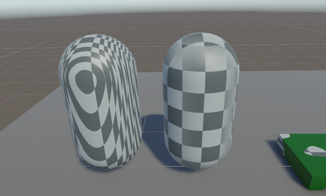
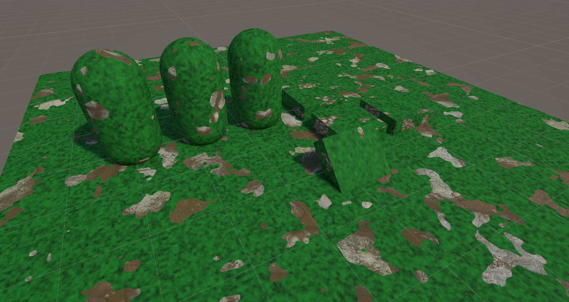
I tried making making a simple triplanar shader that applies an albedo texture. The capsule on the left uses the custom node we built, the one on the right uses the built-in triplanar node. I used a checkerboard texture to clearly illustrate the distortion. The blend value is set to 2. The first image is at ground level:
Next, moving both objects up to y = 100. It looks wildly different, because interpolating from (0 to 100) causes a much faster change in UVs compared to interpolating from (0 to 1).
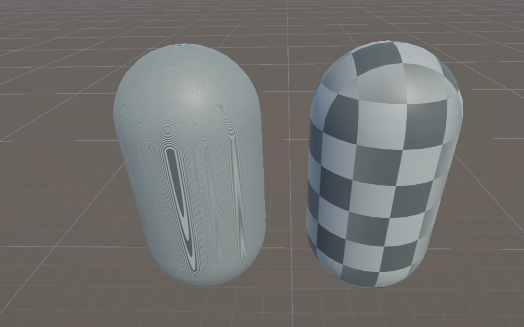
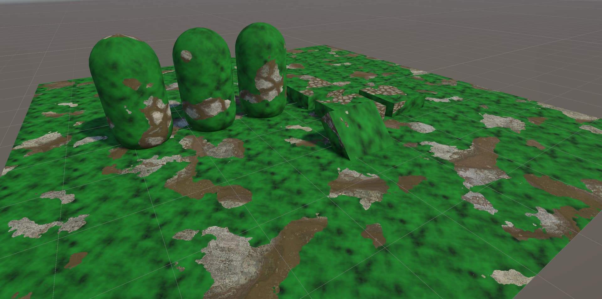
Finally, here’s ground level again, but with the blend value set to 25. It mostly looks reasonable, apart from the severe distortion around where the normals make an angle of 45 degrees between the world axes - there it tiles rapidly.
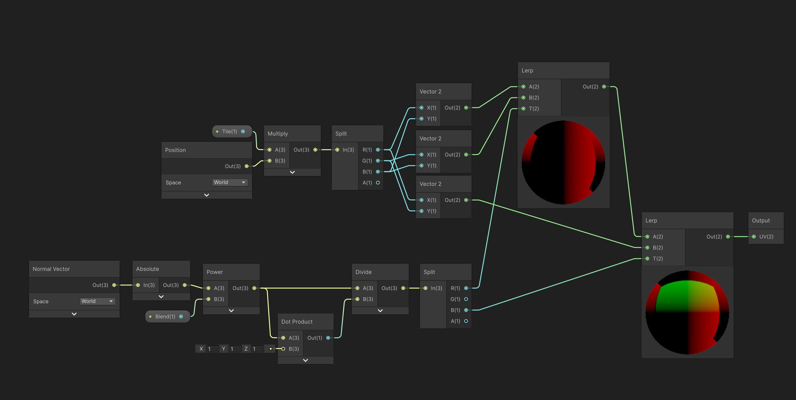
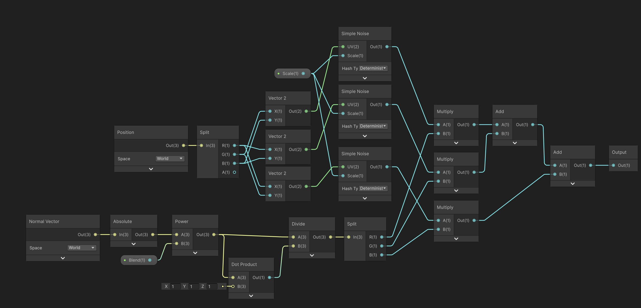
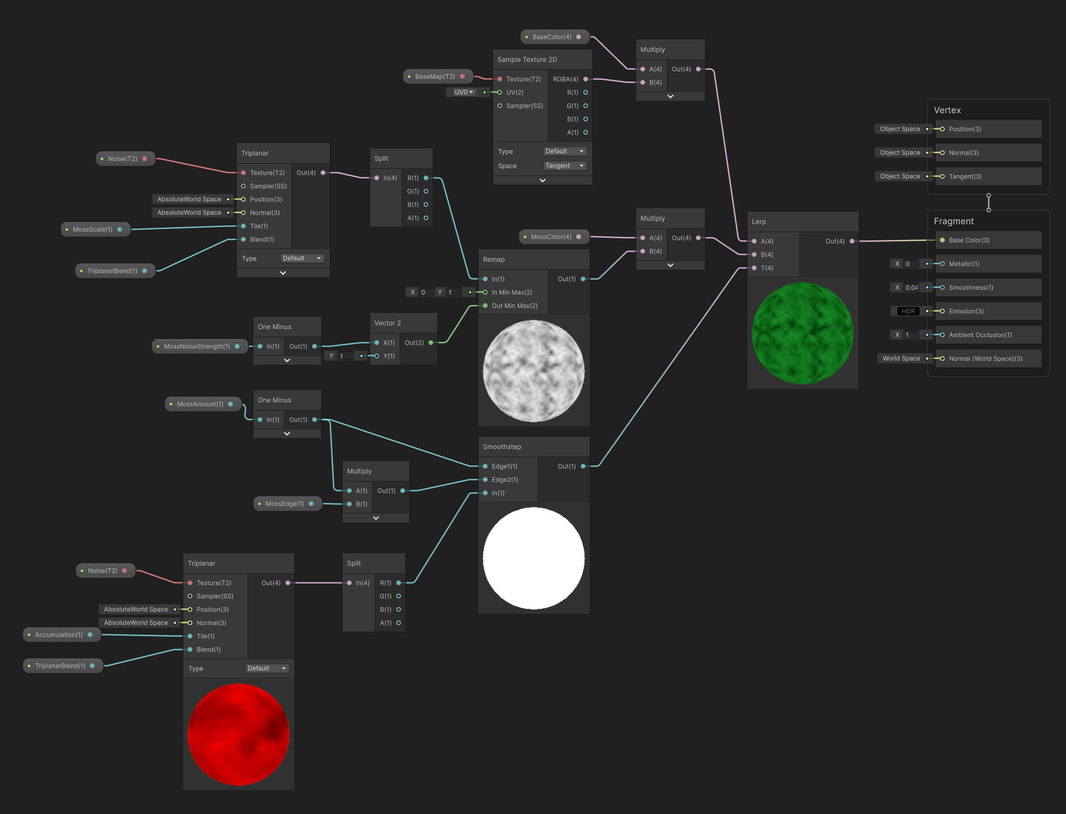
For reference, here is my triplanar subgraph. I multiply the position by a “Tile” factor, which is set to 1 in all these examples, but should otherwise be the same as the course implementation.
What happens if you remove the Tile branch. The graph looks identical otherwise.
It’s quite possible that there is an issue, however. We mainly used this in testing on the bricks and the building with blends around 100. In fact, lower blend values (like under 10) definitely break the shader.
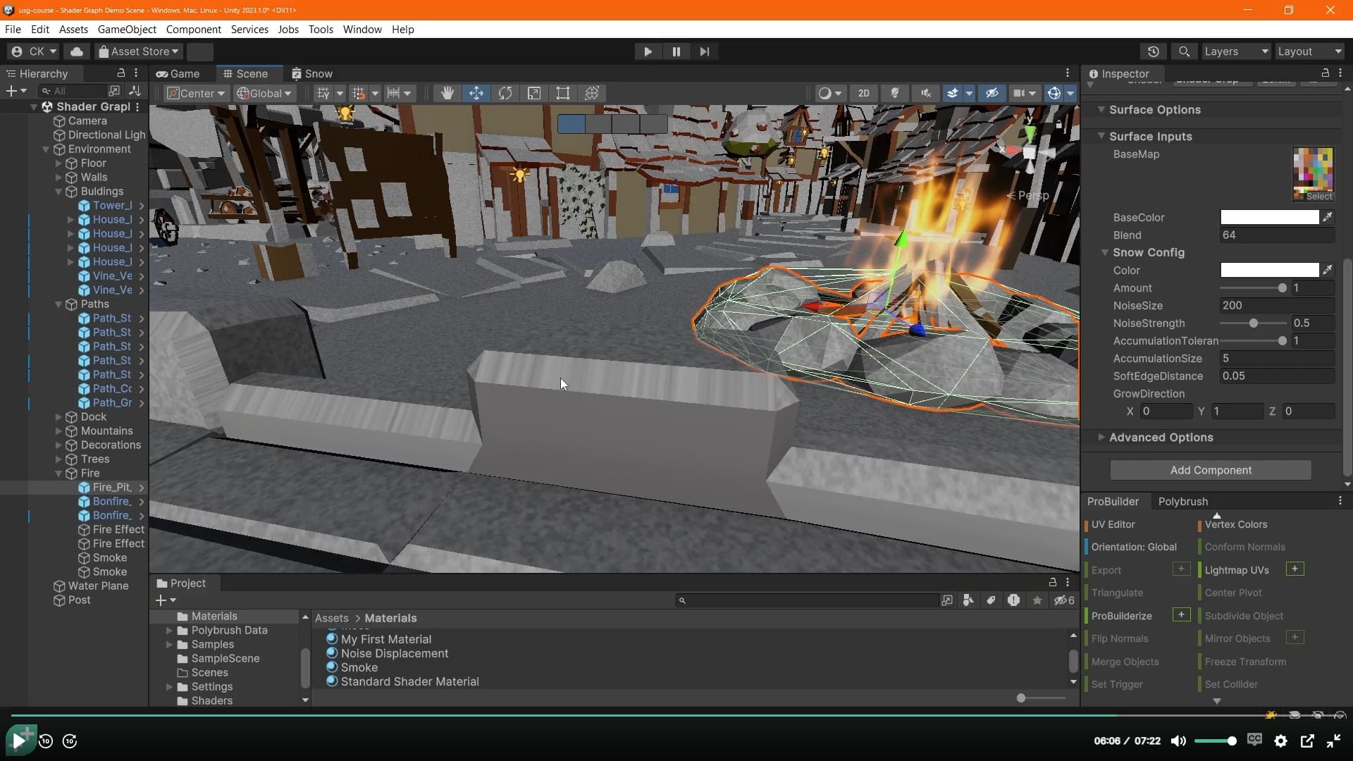
The instructor actually runs into the issue in a future video. 5.2 Snow, at 6 minutes, he points out that there is stretching when the surface is exactly 45 degrees:
But since the snow shader doesn’t require triplanar mapping, he just removes it and moves on.
Fundamentally the issue is that the “blending” doesn’t work. Interpolating world space positions to use as UVs does not blend the textures - the only reason the shader mostly works is because of what the large powers are doing to the normals.
If you start with a normal vector with a biggest component like (0.8, 0.6, 0) and take it to the power of 25, then normalize it, you get something that is equal to (1, 0, 0) up to about 3 decimal places. This results in using the yz-plane to sample the texture with no blending. Looking at the cylindar above with blending set to 25, you can make out the distinct regions that are mapped by the xz, xy, and yz planes, as well as the inbetween areas that are actually blended.
Only angles very close to 45 degrees get any non-trivial amount of blending, since they’ll look something like (0.71, 0.71, 0) and the power function won’t make one coordinate dominate the others, and those are the parts that will get distortion.
I finished the course, but figured I’d go back and fix the shader.
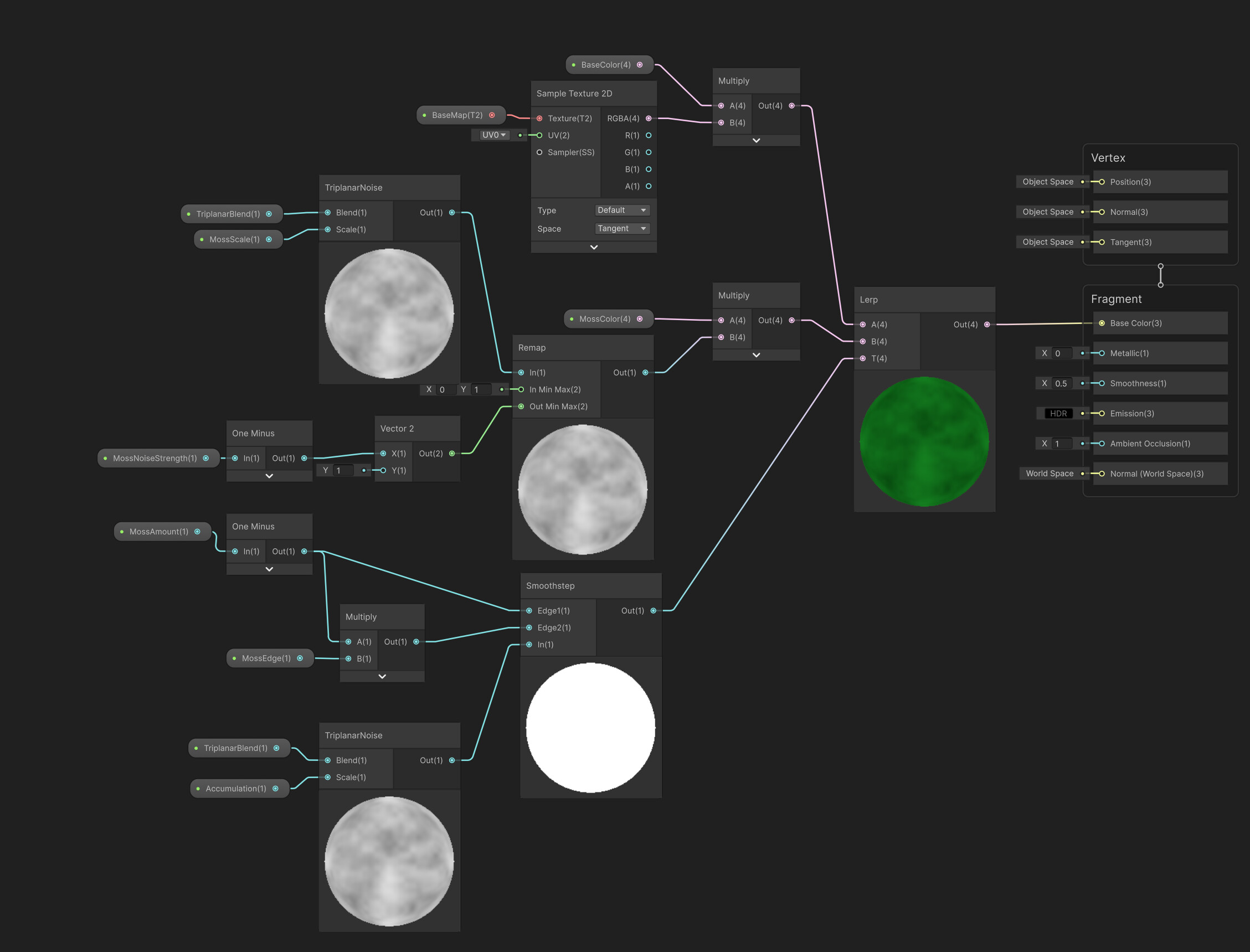
Making a TriplanarNoise node by sampling noise three times and then blending them using the modified normals (this is just normal triplanar mapping, but applied to noise instead of a texture).
An alternative solution would be to use a 3D noise function and get rid of the triplanar mapping altogether, but shader graph does not have 3D noise built-in as a node.
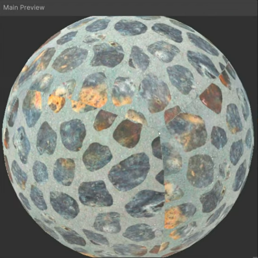
Another alternate solution would be to use a baked noise texture and sample it using the built-in triplanar node, which gives similar results without having to implement any subgraphs:
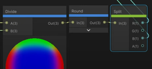
I found a reference for the implementation used by the instructor - it turns out there’s a missing “Round” node on the Normal blend vector right before it gets split and used to lerp. The idea is to eliminate the ‘blend’ region altogether, and instead have every point on the surface sample the texture using xz, xy or yz. This results in a hard edge between the regions.
This is a “cheap” way of doing triplanar mapping which trades off quality for performance by reducing the amount of texture sampling (or in our case, noise generation).