How to make small curved ridges on Children's Block

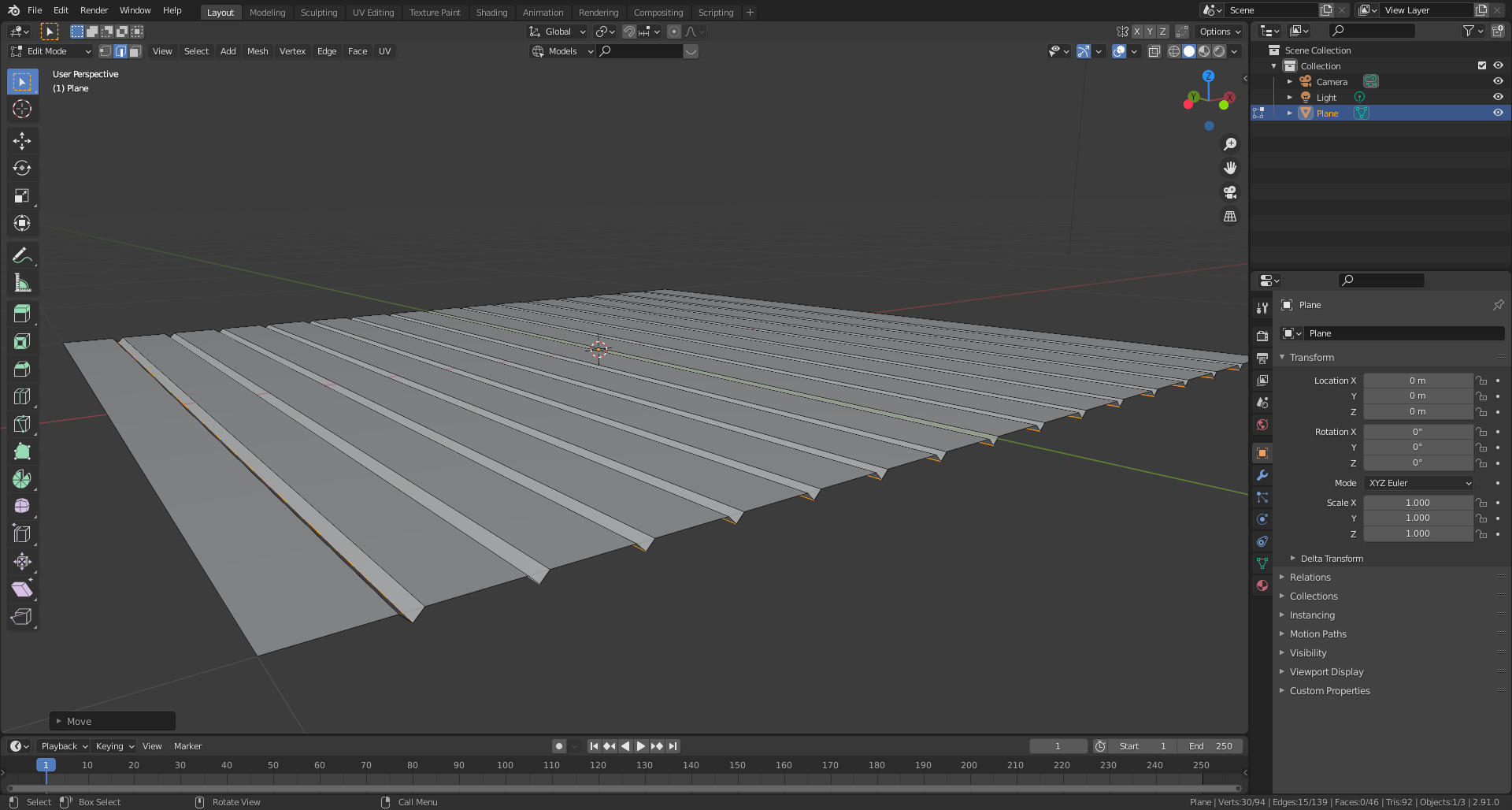
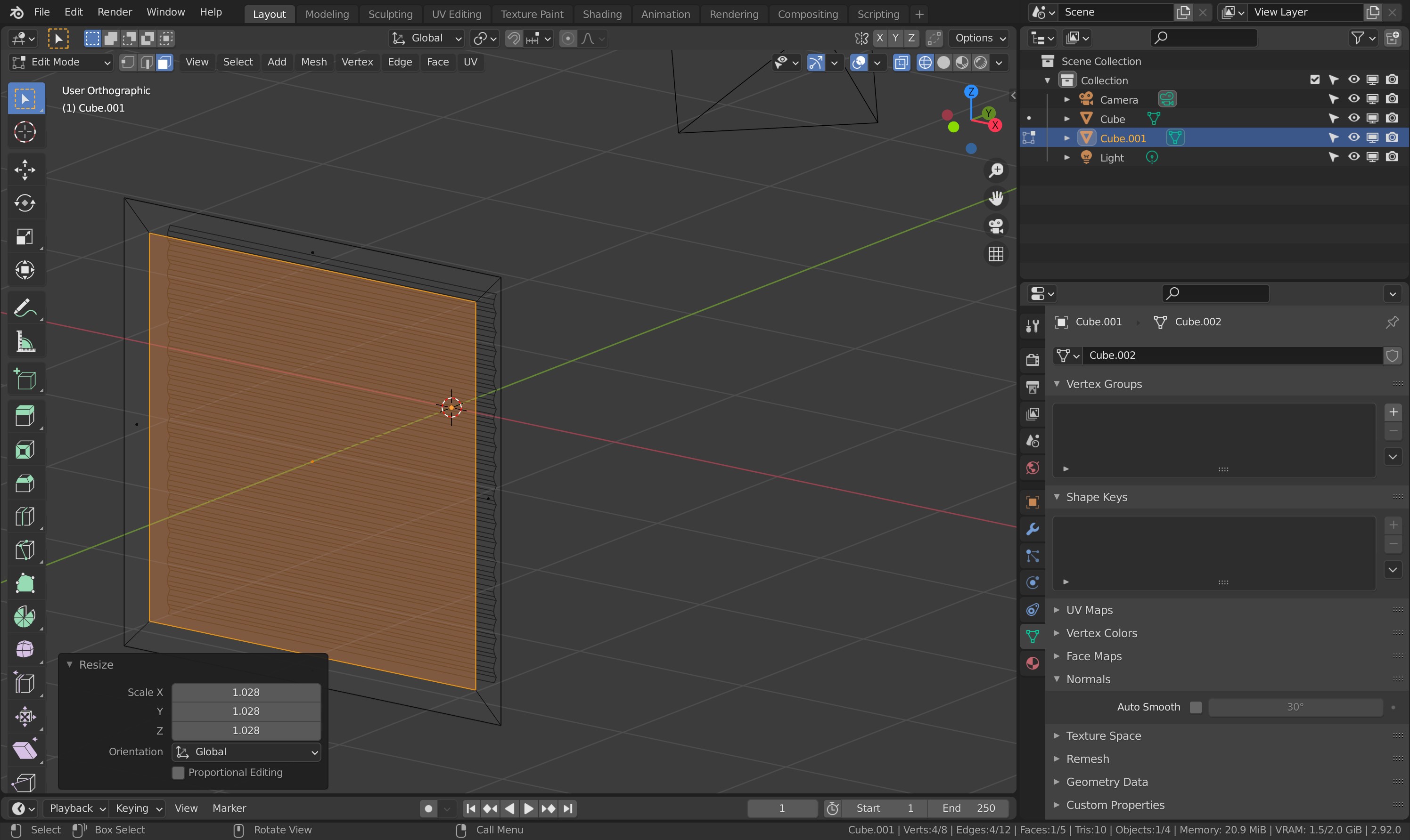
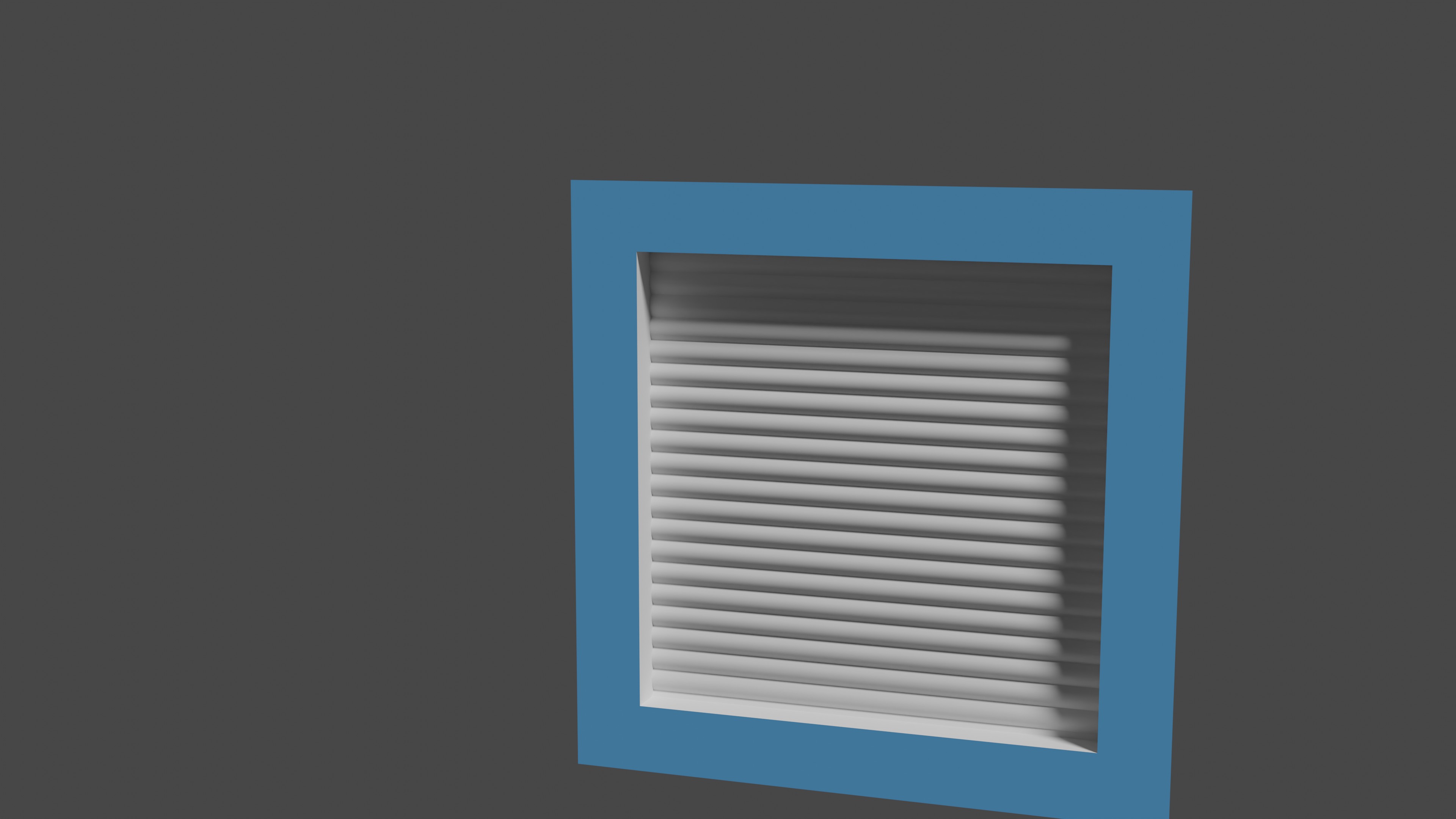
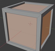
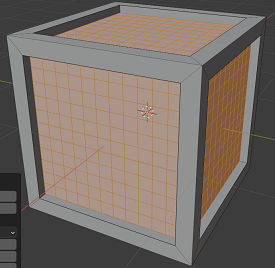
I was wanting to make some Children’s blocks

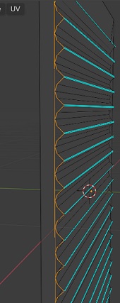
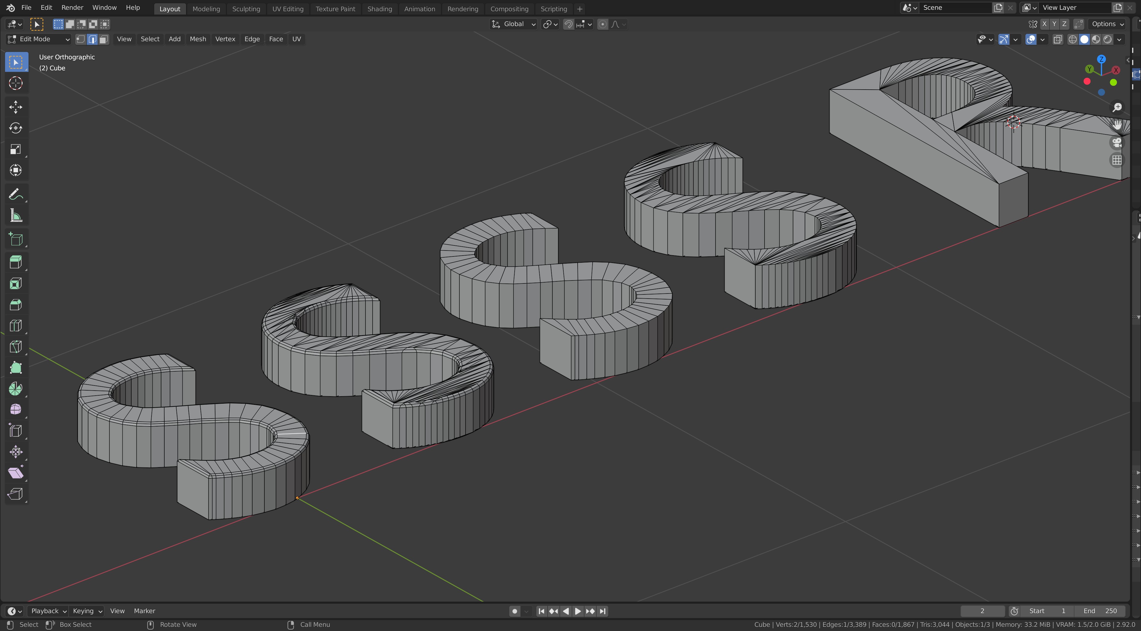
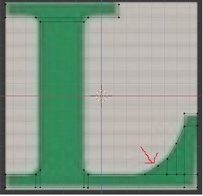
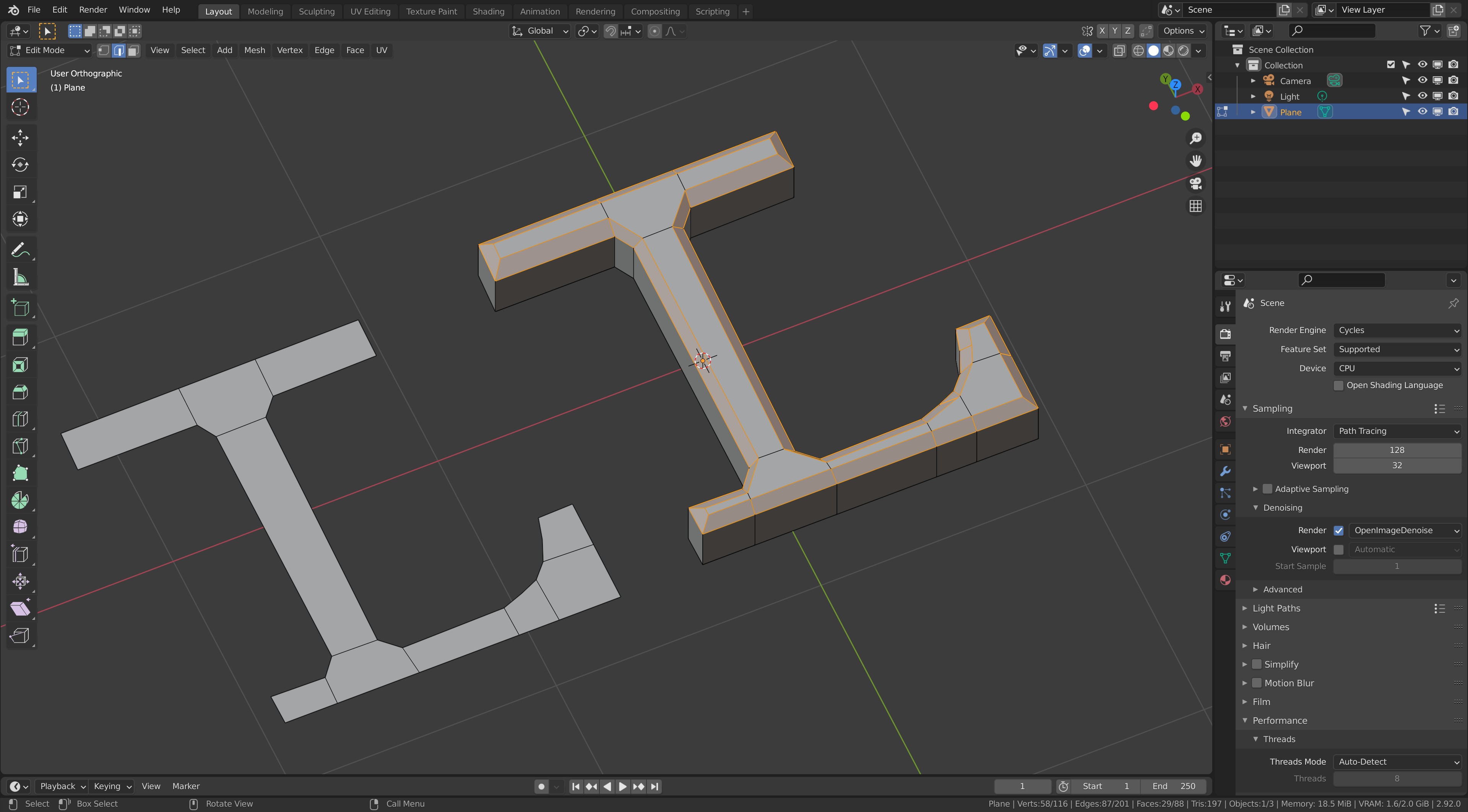
How can I make those thin arced ridges in the inset part? Secondly, I was going to do the letters Z, L and F as easier letters.
Children's Block

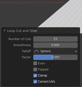
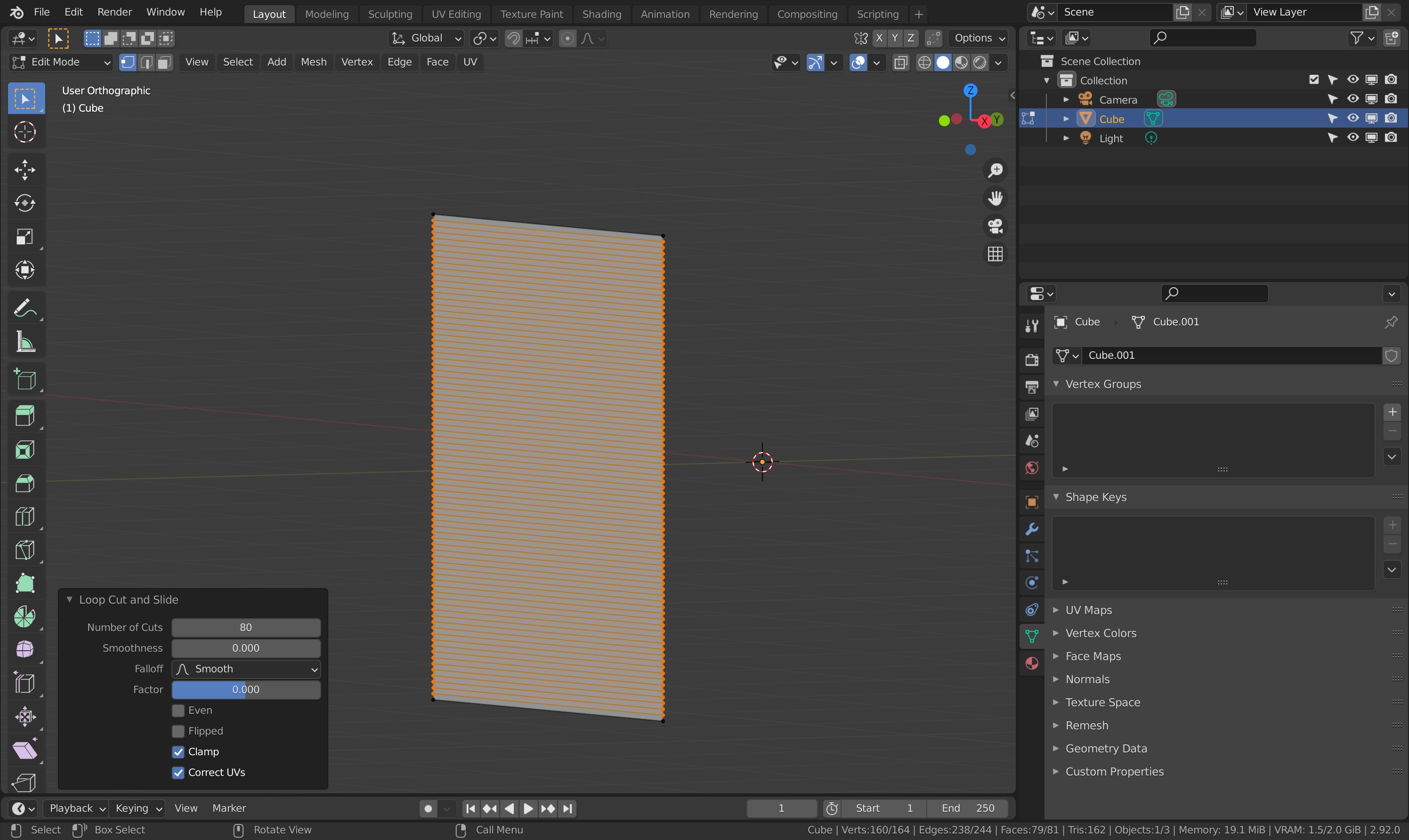
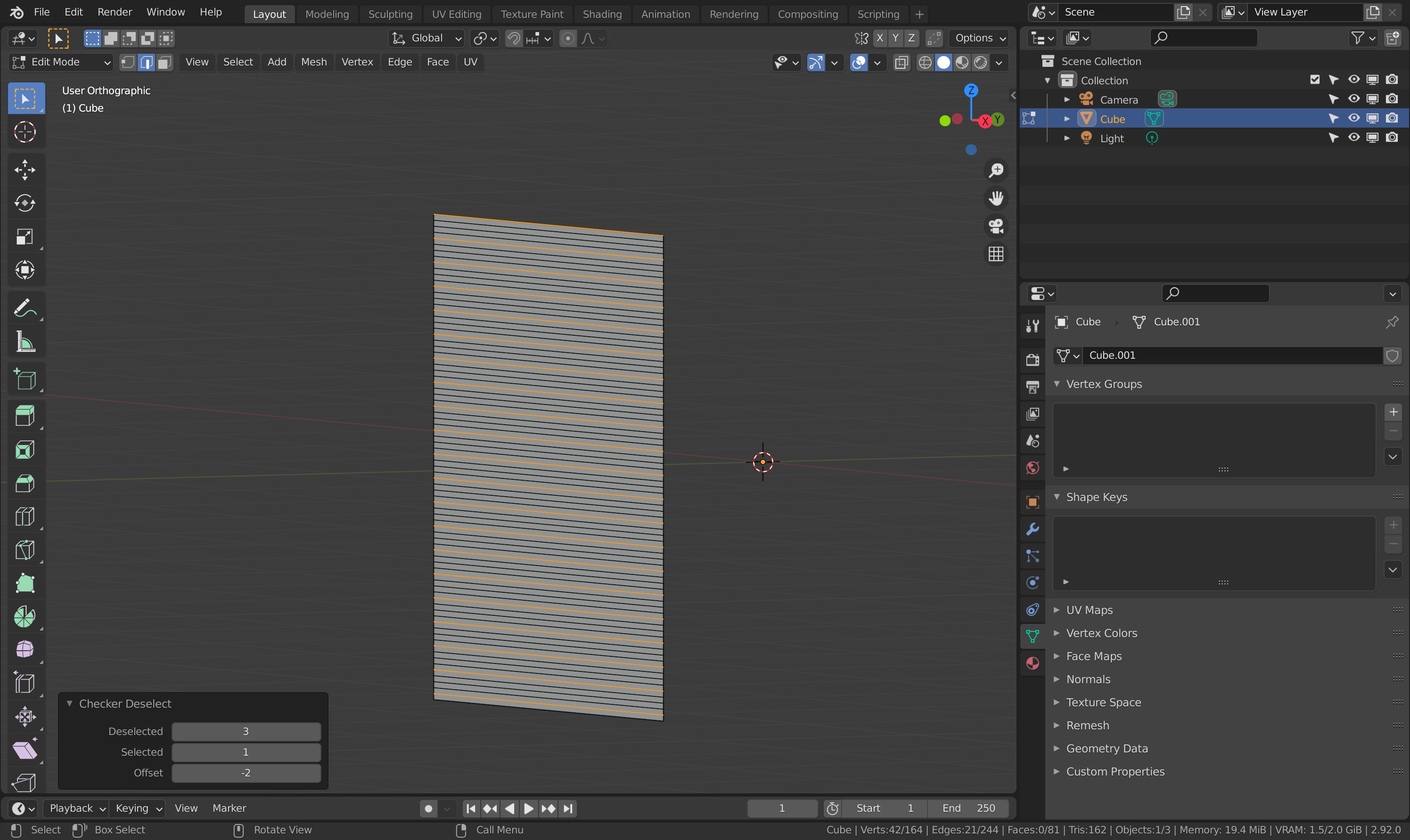
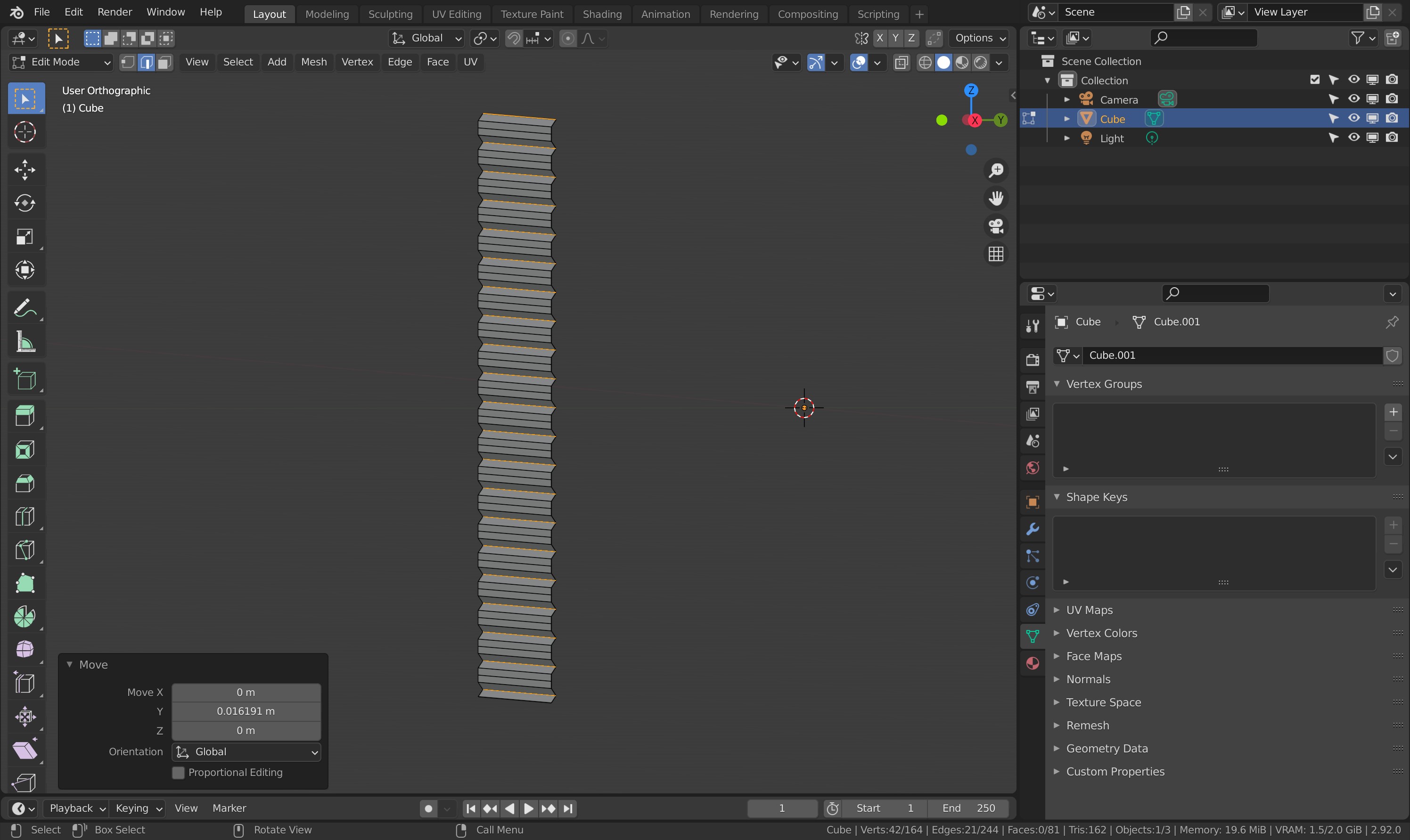
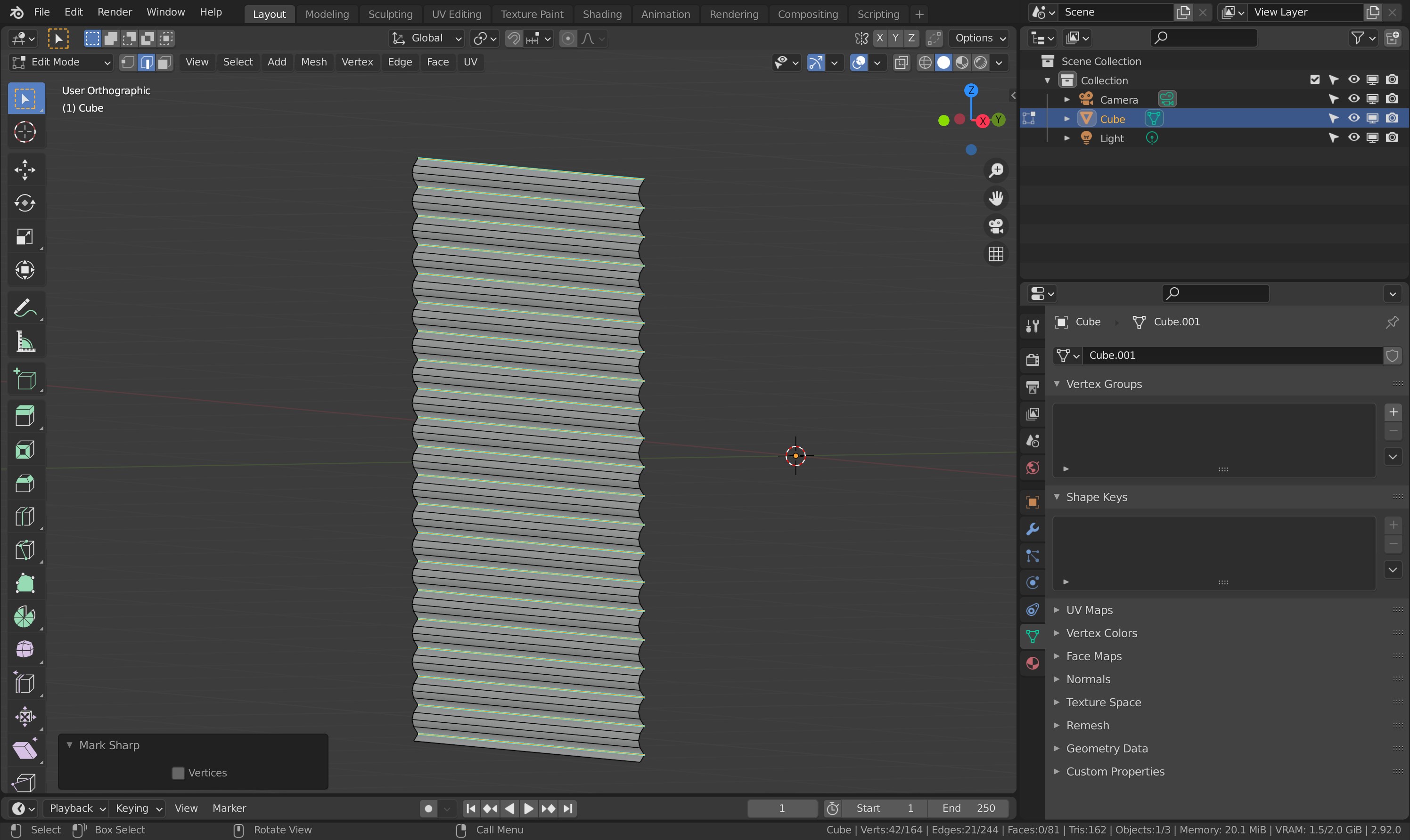
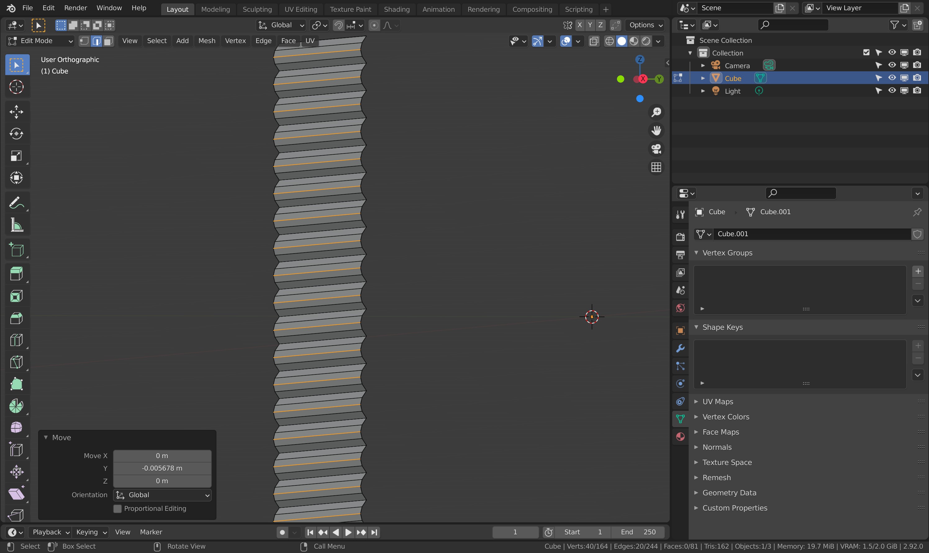
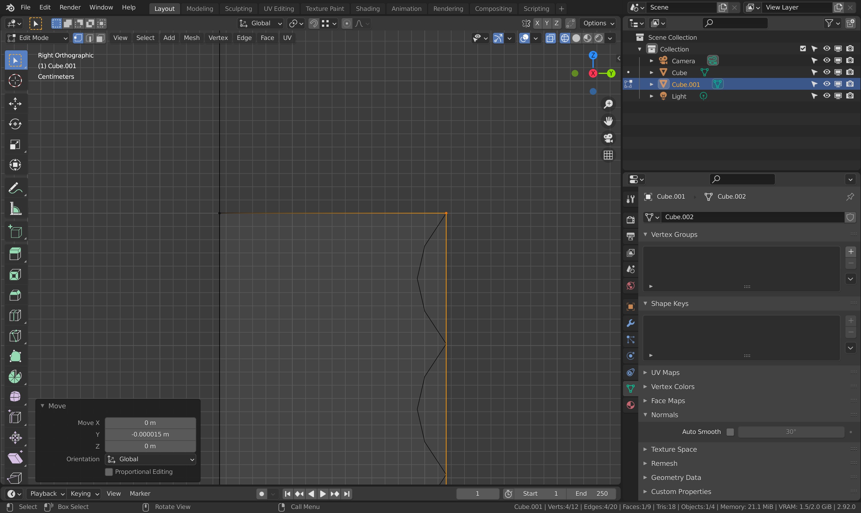
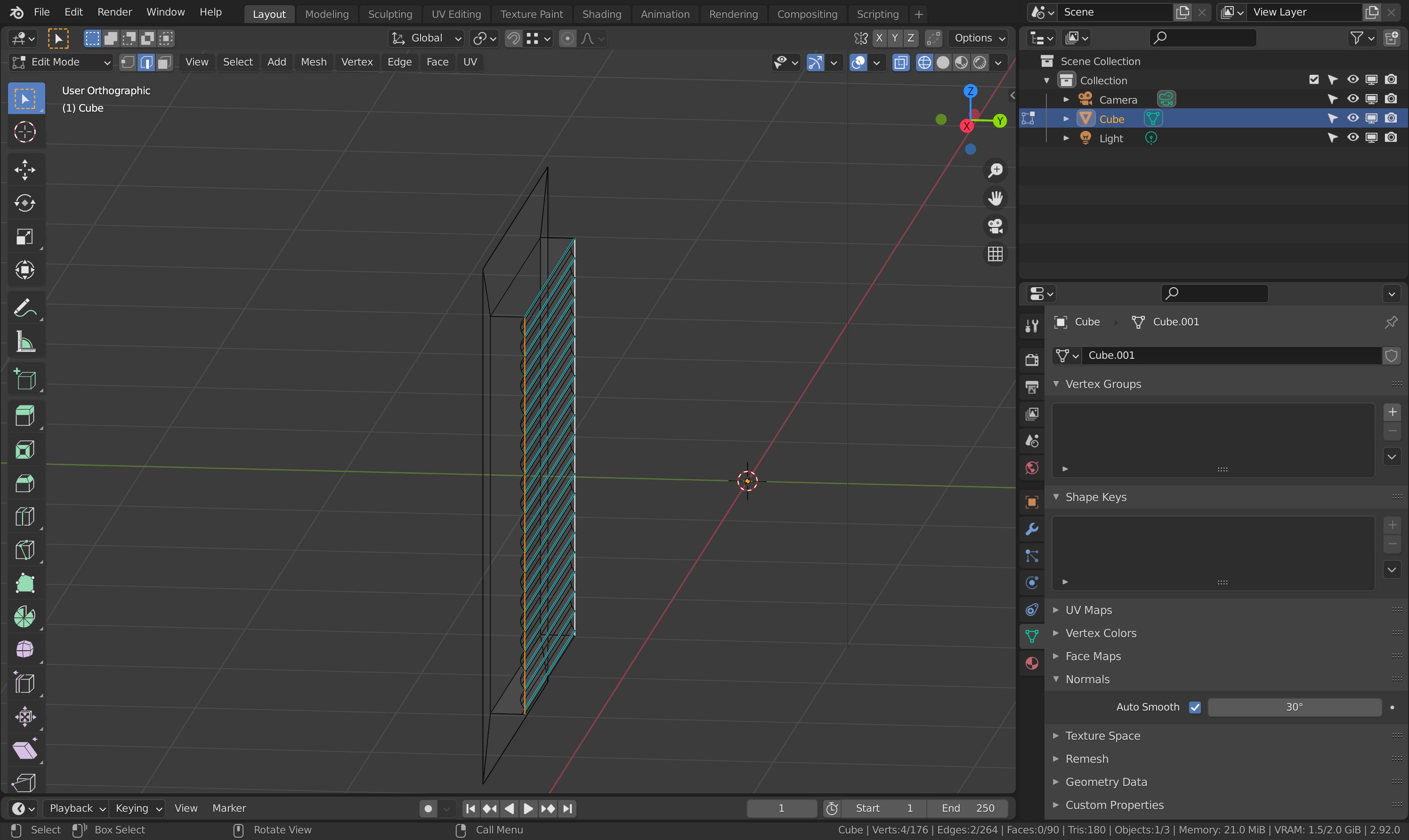
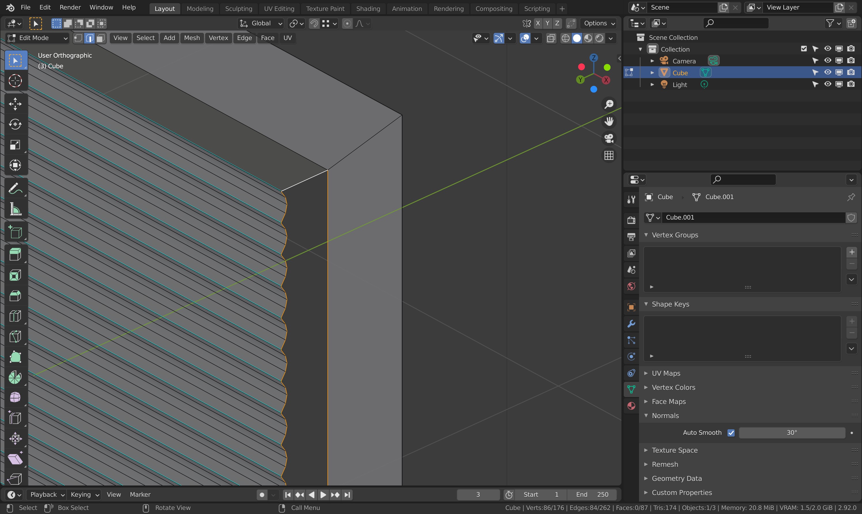
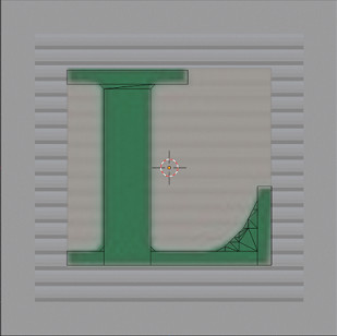
I have the Faces selected and then did Edge/Subdivide but I can only subdivide up to 10. The horizontal Edge lines aren’t close enough together. Subdivide all those again? Then I was going to Extrude the subdivided polys to make the letters, then get rid of the vertical lines outside of the letter to leave horizontal rows and somehow arc the horizontal rows that are left around the letter.
image

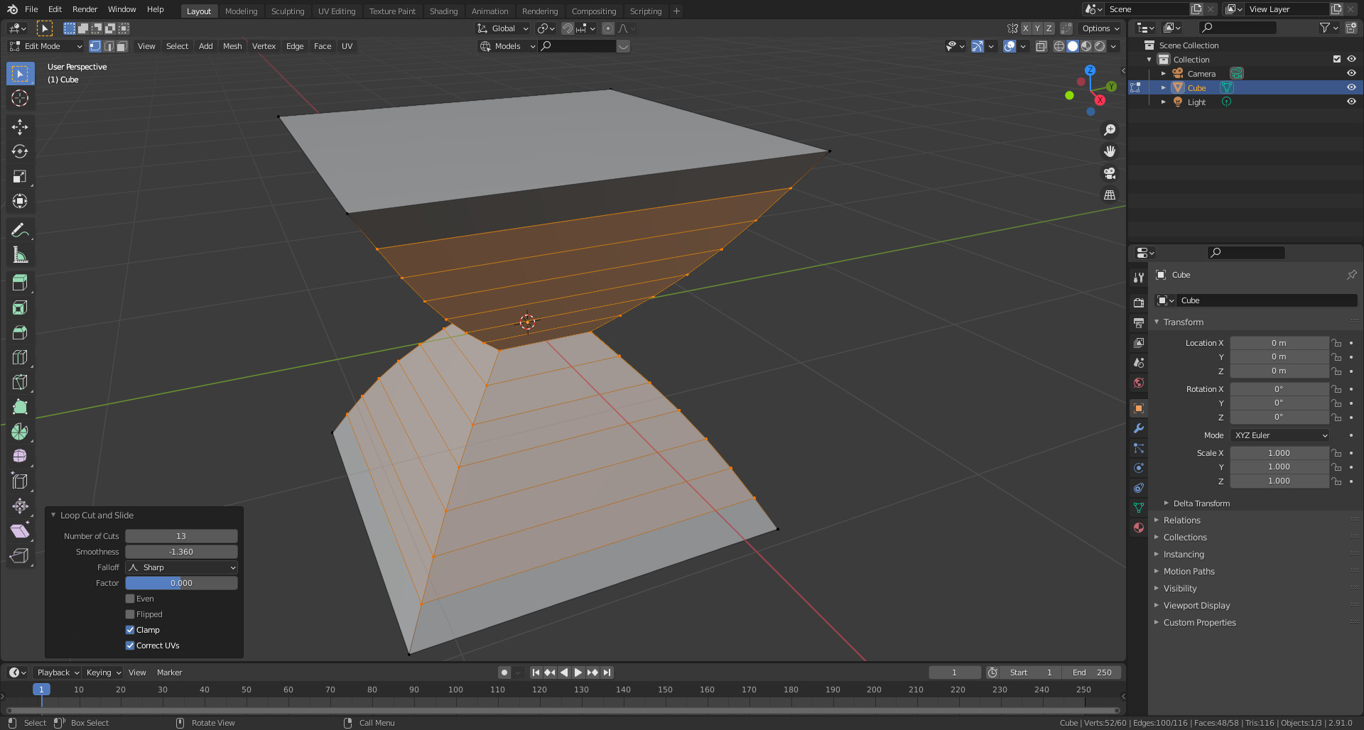
I tried to put in Edge Loops, Control/R but that didn’t work.

1 Like

yes, true. 10 is max.

But, then you can subdivide again! with 10 max.

Does it need to be one mesh at all?

If not, then manipulate one mesh plane (face).
Use edge loop (Ctrl r) to add loops.
Then with edges still selected, use Ctrl b to make duplicate (bevel) edges. Use 0 or 1 … 2 bevels loops.
Select the correct edges to drag then in ‘v’ shape.

Copy the plane and rotate to fill the other 5 sides of the cube.

I’ve added some cut loops and set it to Sphere. I tried changing some of the other parameters but it doesn’t change. What is Falloff and why can I choose different shapes, like Sphere, but the shape doesn’t happen?

image

1 Like

Most would probably just use the normals mapping and fake the backgrouns ridges.

However I always prefer real geometry!

You can sbdivide higher than 10 in the panel just by typing in the number you want.

However in this use case do you want to subdivide?
Why not Loop cut? Crtl R. scroll wheel up the cuts. Then also alter by the panel for specific count.
Ah you have thought of that while I was away doing this. lol.

Loopcut.


Edge selected, checker Deselet adjusted in panel.

Pulled back, bottom of ridge pattern.

Mark them Sharp

New Checker deselect manipulated to be the mid top of the ridges and mover forward a fraction to shape.

New Cube, back verts deleted as before, Scaled up bigger for block outside, the inset to fit the ridged panel.

Close up extrude back, snap to the vertex of the other panel object.

Join both objects. Delete the long back side edges.

Select the edges of ridged panel side and outer block, recreate the side face, repeat other side.

Result! one side of a block that can be duplicated and a cube built up from.

2 Likes

The smoothness has a relation with the falloff type. Which works on edge loops, not on a edge.

Started with a basic cube.

@NP5 When you say above to join the two objects…what do you use to do that? I’ve used Bridge Edge Loops. There’s Control/J in Object Mode. And something about using a Boolean Modifier but that doesn’t look like what I should use.

@FedPete thanks! Edge loops not edges. I’ll mess around with a Cube but I think I see how it works with that pic you put.

1 Like

To join two objects you use the Ctrl J as you mentioned.
I just found it easier to make my second cube, scale it etc. in a new object. As joining is easy when ready. I could have added the new cube mesh in the first object too. Just the way I happened to do it was in separate objects.

I found that I couldn’t just select both objects at once, Control/J(oin) won’t work, you have to select one and then the other, like when parenting. In case another newbie reads this.

Other thing I knew would happen if that back Face of the extrusion is still there behind the arced used-to-be-object. Do I need to dissolve or delete that Face. Or would it have been better to get rid of that Face before I Joined the two objects? I know it’s only one Face but that’s 4 extra Vertices too. And should I be in Vertices Select to get rid of the Face rather than Face Select?

Well yes that is what selecting both means select one then another one. Sometimes you can box or circle select them in one go. Then Ctrl J.

Yes delete any face, edge, or vert not wanted.

Deleting a face may not need the verts deleted, they may be holding other edges or faces too. So you delete as appropriate. You can play safe and delete face only. (face select mode probably preferable)

If verts are doubles, like having snapped one bit of a mesh to another, the standard M, by distance, will clear up any verts left over from only deleting the face.

I thought my image series should show enough?

@NP5 I did box select both objects and it wouldn’t join them. It was only when I selected one object then the other that it would join them. I hadn’t expected that to happen so I mentioned it in case others tried.

I carefully selected all the side edges on that long side (checked that the vertices weren’t connected to the long edge on the apex of each arc) and then Face/Fill. Did I do something wrong to make it not fill?

Edges selected but will not fill the Face in

Figured it out…Vertex/New Edge-Face from Vertices worked.

Last thing is how to put a letter on the arcs. Maybe make another Cube, delete all but one Face like before. Make the letter and Join the objects?

1 Like

There is a Blender text creation option. However, it is not nice imo. You could try it if you like. Standard Shift A for add, then select text. Go to edit mode, backspace the word text away and type the letter you want. Back to object mode and convert to mesh. Into edit mode and see the horrid triangulated topography, select and extrude a height. Works fine but a nightmare if you want to bevel the edges due to the topology.
I would probably start with a cube delete all but two verts, one edge. Then square on to them extrude the edge out like it was a pen thickness of a line writing the letter you wanted. Rotating the edge as need be to go round the letter shapes.

See results both ways in the image. The bevel on the triangulated is a mess but may not show up well.
Hint, I used the Auto produces S as a template/ reference, by doing it over the top, to follow with my hand made by edge extruding.

1 Like

Yeah I agree with you. Those letters are kinda horrid. lol

I went ahead and did my own letter. I made a letter and Image as Plane. Wasn’t too bad. pic below isn’t joined yet. It’s a Face from the Cube again. Not sure if I should Extrude the thickness on my letter before I join it to the arc Face or not? pic is just showing the letter Face with the Image reference plane behind it with the arc Face behind that.
image

1 Like

You have some, lots, of tris. I would get rid of them. If the top is to remain flat you can even get away with merging them all into one. Though I would then break that up by chosen J joins across pairs of verts making several Ngons. Or you will have problems beveling the top edge. Select the top outside edge and try beveling it as it is to see what I mean.

1 Like

Is this better? Is it kosher to have a quad like the one that the red arrow points to?
Quads to make a letter

And yes your pics helped tons!! It’s just because I’m a newbie on learning graphics. I really appreciate this help and I’ve got a very cute thing to do in the animation with these blocks :slight_smile:

2 Likes

Yes that vert is fine.
Yes much better generally. Assuming you add a bevel to soften the top outside edge, If it is small it will be fine. If you make it a stonger bevel the tight close verts at the base of the upright might cross over each other, messy, surface glitching. If you join across the upright at the base end like you have at the top, you can remove the edges that continue on down the upright.

Ugh words. See image. lol easier to show than tell.

Very strong bevel to show that like that the bevel geometry avoids crossing itself. You do not have to mimic what I did there exactly. I hashed it up quickly. Flat surfaces that will not be bent, curved, etc. do not worry about ngons.

Edit, to see what I mean, extrude up your current ‘L’ and bevel its outside edge.

1 Like

Yes, I see what you mean! All these things have really bumped up my knowledge overall for the basics on any modeling project!

2 Likes

Privacy & Terms