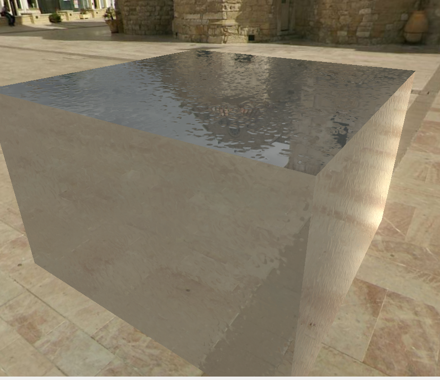
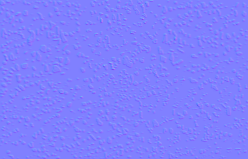
I’ve been working on a different project but it also uses a lot of techniques from this part of the course including normal maps. I have a wall texture I’d like to use as a normal map but it isn’t behaving as I’d expect. Specifically, shadows and highlights not appearing in the expected places based on the lighting, and some surfaces where I’ve applied the normal map appearing as indentations rather than raised bumps as I modelled.
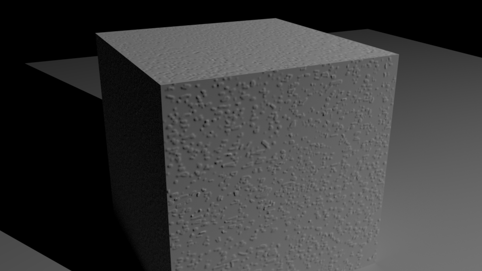
Here the close side of the cube shows the texture from the normal map as I’d expect, but the top surface appears to be indented.
I also made a couple of animations with a light source moving around the cube which somehow don’t appear right:
I’ve spent a bit of time rotating the normal map, increasing the thickness of the shapes in my model and then re-baking. Feel like there is some fundamental element I’m missing here. Any ideas?
Are all your normals pointing outwards? That’s the only thing I can think of. I did a quick test myself and everything works just fine if I utilize normal map node on my cube. Even if I rotate the sun lamp.
Yes, the simple cube I used the map on was just the default cube created from scratch, and modelling the surface texture I only used the “add” sculpting tool so all normals should be correct. Some faces on the cube do look correct but the top one not always for some reason.
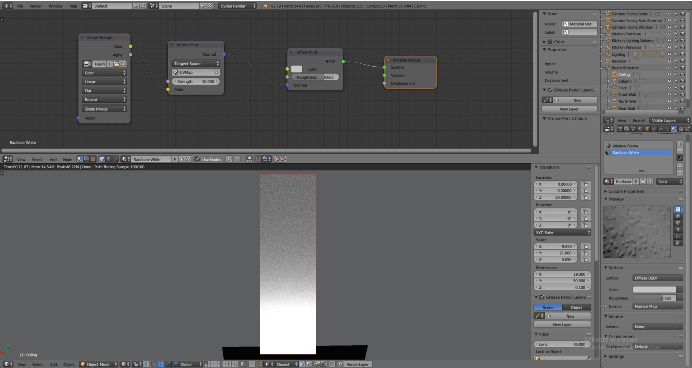
There’s at least one thing, but I don’t know if that would solve your issue. In the Image Texture node you should always use Non-Color data because you don’t want the color space conversion to happen if you are not using color information. You are actually interested about the values texture has has on certain UV coordinates. Other than that, I used the same setup. Maybe it’s your normal map and/or how you baked it?
I think you may be onto something with the normal map being odd as we have exhausted all other options.
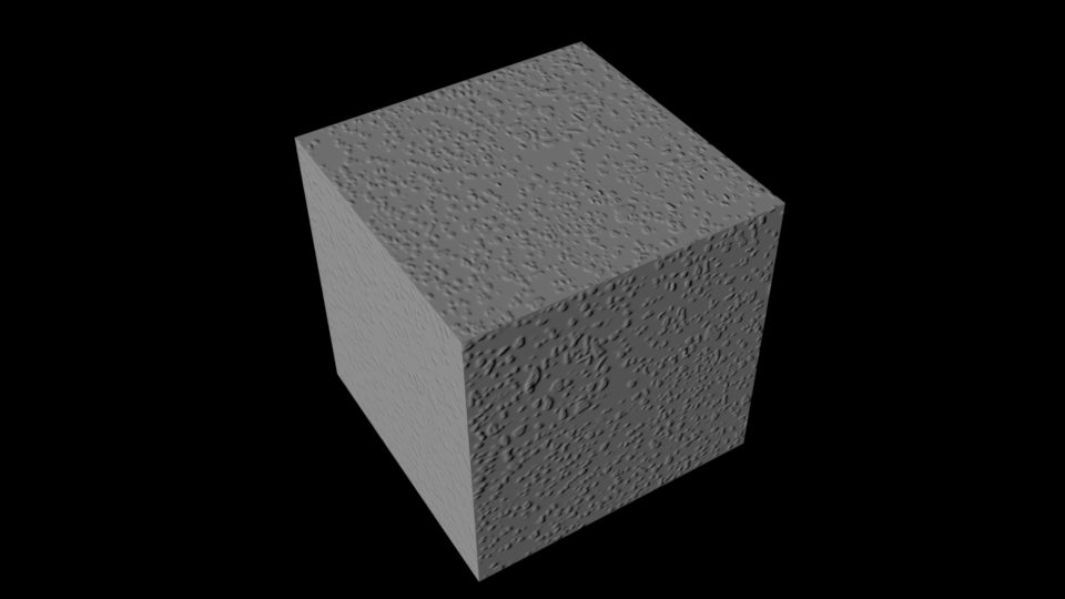
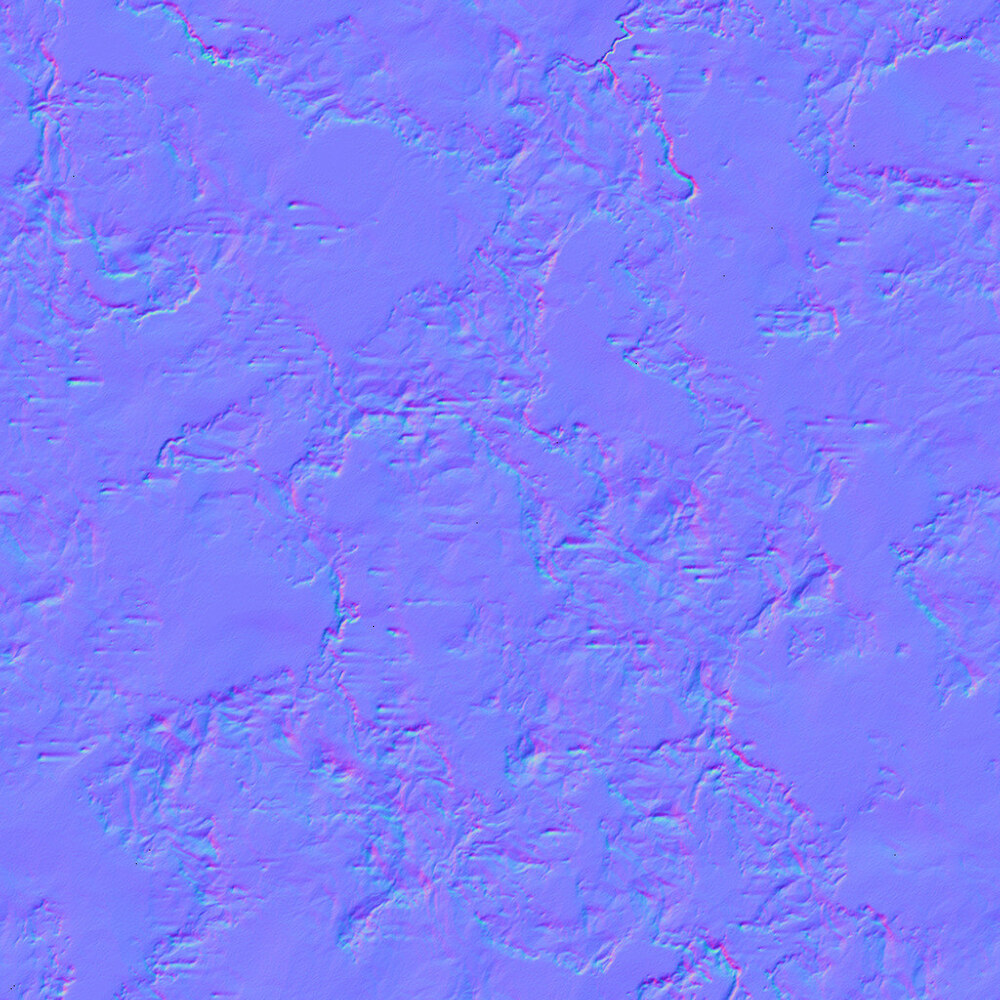
Today i used a basic cube with the exact set up and switched between two different normal maps one created this inverting the other did not.
This is his normal map. I tried it as a jpg in case format was an issue.
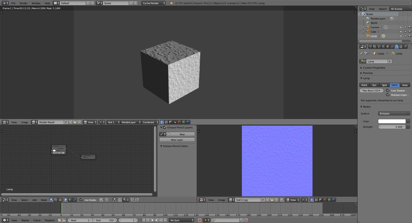
Hi Jax, actually I just reused an old screenshot of the node setup and already did change it to non-color data as Marc suggested on Discord. Still seem to have some indentation effects as before though.
Here’s the blend file. I just chased up a suspicion that there was something wrong with the lighting, and found that the Camera and Lamp were on layer 1 and the meshes on layer 5, but in the end it didn’t make any difference when I moved them all to the same layer
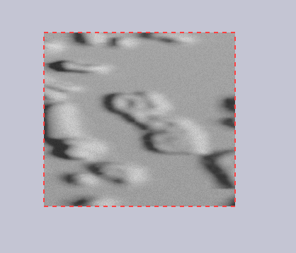
Here’s a good mini example of what’s going wrong. The directional light is directly “north” of this surface here. Why are the shadows on the “west” of the bumps? It makes no sense if the normals have been generated correctly. In mild cases like this where there appears to be a 90 degree offset it doesn’t look so bad or unrealistic, but when the offset is 180 degrees then due to the shadow/highlight illusion it looks like indentations rather than protrusions.
It hard to say from your screenshot where the light is actually coming from, but that could be a correct thing, but hard to say. You do know that directional light has only direction, where it is positioned do not matter?
OK, maybe I’ve solved this actually. Just noticed that I introduced the normal map node with the mapping type set to object space - changed back to tangent space and used my UV map and it is looking correct now. Wonder how I didn’t get this working before - I tried every different combination!
Will render out that animation again and see if it all still looks correct.
To me the normal map looks inverted but yet playing with the spot rotation changes things.
Did notice though that in blender it looked inverted but in my xsplit window it looked fine.
 Any chance I could see the HP and LP models?