Question to Posing the mech 0:52 (axis problem)

Hi there,

I am currently building my mech, following Grants instructions. In “Posing the mech” he suggests to scale the lower leg along the local z axis. When I double type z to get to the local axis, it is shown at a totally weird angle (about 80° from the real z), not along the objects normal as it should be.

What did I do wrong and how can I fix it?

Thanks

Goemoe

You probably need to change the Transofmation Orientation to local space in pose mode. Perhaps it’s using global space.

In the viewport, press the comma key " , " and then choose “Local Space”.

image

1 Like

Welcome to this site.

Please give full screenshots with any questions. With the relevant panels open.

This can be done by Blender itself, via the ‘Window’ menu bar top left hand side. On that menu drop down is ‘save screenshot’.

My guess is perhaps the local axis has been lost by applying the rotations and scales.

In which case, I would extrude the end face to make it longer and then remove the now loop that was the original end you extruded from.


Hi there,

I guess I lost the axis by applying the rotation and scale. I had hoped there is a way to undo it later. Thanks for your replies! I will either extrude it or rebuild the part again. :slight_smile:

1 Like

It is one of the rare occasions when applying the rotation and scales works against you. There are tricks to create the local axis anew, but far more complicated and messing about than needed on simple objects like this.

1 Like

Ah ok, when I saw “pose”, I assumed the model was rigged.

If you can find a place on the mesh that is either parallel or perpendicular to the plane of axis you need, you can still work with the mesh by using the 3D cursor.

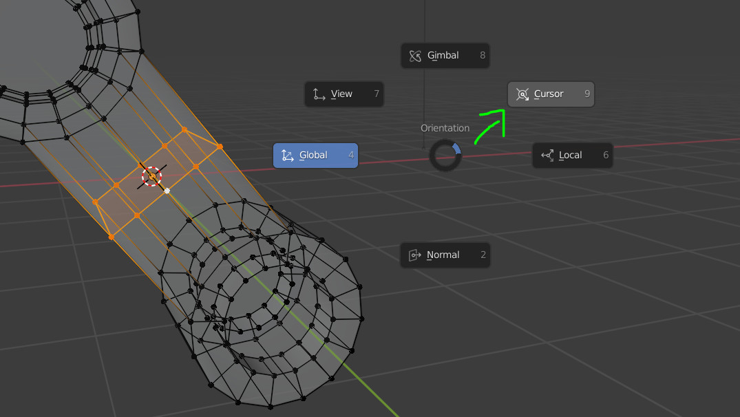
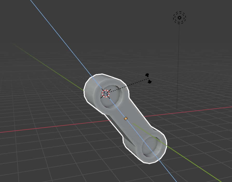
In the image above, I selected the 3D cursor tool and changed the Orientation to “Geometry”. This allows me to click on a surface and the 3D cursor will adopt the rotation of the surface it snaps to.

I added a temporary face inside the mesh which I can click to snap the cursor to.

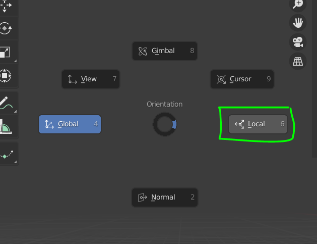
Now I can translate, rotate an scale using the orientation of the 3D cursor if I change the Tranlation Orientation to Cursor. Press comma (" , ") and choose “Cursor”.

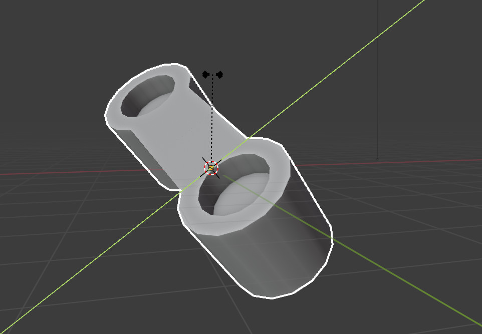
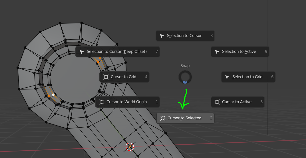
For example, now I have an orientation I can use, I can press Shift+S and snap the cursor to any point in the mesh (without the need to add more unnecessary faces). The Cursor orientation won’t change unless I snap it with Cursor tool to another face which has a different normal value.

It takes a couple of steps to get the right orientation for the 3D Cursor but once you get it, it’s a neat trick which I use all the time for flattening sufaces and rotating groups of faces which aren’t straight along one axis in World Space.

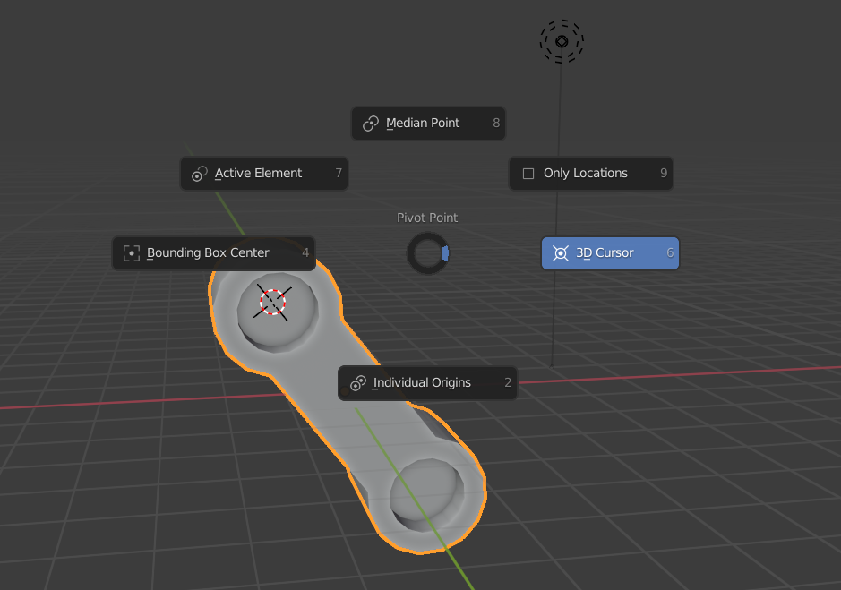
Then you can use the 3D Cursor also as the Pivot Point.

By pressing fullstop/period key, it will open the Pivot Point menu. There you can choose “3D Cursor”.

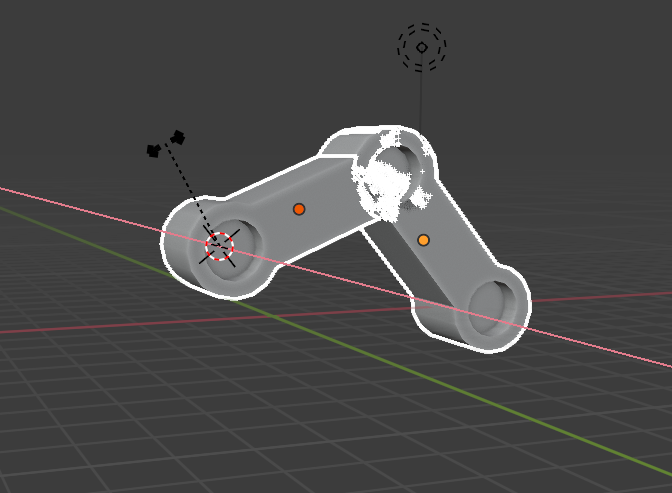
This will help you pose multiple objects at a time from a fixed location AND with orientations that match the correct orientations.

image

Hope you find it useful!

2 Likes

Hi Mark,

thank you for your effort! It took me some attempts to fully understand and reproduce your “lecture”, but it would have worked (have already rebuild the part for the mech) for sure and is a great help for future alignment problems.

It is a really useful trick, thanks a lot!

2 Likes

This topic was automatically closed 24 hours after the last reply. New replies are no longer allowed.

Privacy & Terms