How to avoid corner distortion when applying curve to mesh?

So, part of my cityscape plan is roads around the edges. I already made a straight road piece and am now up to creating a corner road piece, unfortunately the bevelling I did made it impossible to create a curve out of the road profile so I have to apply the array+curve modifiers to the profile mesh and curve it around by 90 degrees:

You can see the distortion that happens, presumably due to the very corner of the whole object having a width and overlapping many times. Is there a way around this? Or is it only possible to do a completely smooth and unbroken corner like this by applying a curve to a curve?

Seems like I run into the same problem even when applying a curve to a curve, in the corner. If I offset the corner a bit, it mitigates the issue slightly, but then the shape of the corner is messed up.

I am not sure this will work but this is something I saw in another video using the spin tool, which is also the same principle as used making the bowling pen. I used with a line of verts so not sure how it will work with a curve itself. You may have to convert the curve to mesh before you start. If so, just duplicate your curve, move it to a new layer and work on it there to leave your original intact. Select a single vert as your starting point (where you want to spin from)…Shift S…Cursor to Selected…then select all your vertices. Select Spin Tool…you will probably have to fool around with the settings…like set the curve to 45 or 90 degrees…number of sections you want etc.

P.S. I did a quick search on YouTube (didn’t really watch), which might be of interest https://www.youtube.com/watch?v=2qoC5pdgTLM&t=29s; https://www.youtube.com/watch?v=3481ueuDJwQ&t=8s

Some very good tutorials there! Yes, I think the main mistake I made was forgetting about the spin tool. That seems to be the best way to do this, and the video in the first link shows some good ways of doing the UV mapping of textures for these corners.

Thanks!

Excellent! I am glad this worked for you. Sometimes my thoughts about solving issues are not the best method of doing thing! ! :christmas_tree:

Right side is the previous attempt.
Left side is what I just created using the method in the first video linked. Maybe doesn’t look a huge amount better but it was far more methodical and precise in the process of creation. The geometry is far simpler as well.

1 Like

I think the one on the left does look much better. You can see the difference between the two…the upper right hand corner of the image on the right ,where the small curve is, is not as precise as the one on the left.

I think you did a great job modeling this! Keep up the great work.

1 Like

ughh how did you get this working; i tried making a road only as a test for the lecture, cannot get any solid results! the meshes change their width but to not conform to the curve in any way!

I made it out of a cube so it could be more then a texture but Mikes example uses 3d profiles aswell…

I cant even get a decent example screenshot because for some reason even when I lock the Z axis my curve points are moving to complete random points in the Z axis, which just started happening now. very unmanageable.

The only difference from the lecture should be that for a road you would want to do a deform in the x axis instead of Z like mike did.

Alrtight after starting from scratch i got some reliable results by scaling my cube on the Y axis instead of X; thats where i screwed up.

Then i had to make sure the curve resolution was set to 1, cuz thats an important step for this technique.

Only problem now is that random Z axis moving, which started happening on one side of my curve again. When I changed to 1 curve resolution it became evident there is something wrong with that end, but i’m not sure what.

Maybe I should just not work on that side of the road? anything i do on that side gets deformed in wierd ways, and there is an extra handle on that end for some mysterious reason, of upon which extruding from it gets the problematic results:

Deleting that handle just results in an extra handle every time.

Christ not again! When i extrude EITHER side now it either detatches the verticie or goes wacky in the Z axis.

The roads deformation seems to have something to do with the location of where the bevel is in your world…
But moving it around destroyed the curve entirely!


^bevel verticie going wacky despite being constrained to the XY axis

Hey Steve,

I’m not sure what you are trying to do in your scene exactly, it’s a little confusing to me. I’d recommend making your road modular out of different sections that you then put together and not just one big mesh. Secondly I’d recommend watching this video, which explains the technique I ended up using for the curved sections: https://www.youtube.com/watch?v=2qoC5pdgTLM

its not just one big mesh however one big mesh would be more sensible for this instance, But I dont know how the curve is effecting the mesh anyway so I havn’t tried it on a subdivided mesh, which seems to be the most logical usage of the curve deform modifier.

Do you know how the location of the curve is effecting the road? It only seems accurate if I move the curve inside the mesh, but when I do this, the curve verticies go completly wacky on the Z axis when I try to move them.

I really hate digging through youtube videos all day instead of staying on one track, but I was gonna try to check this video out anyway… despite it being 1 hr… :confused: and guy probably sniffling on drugs.

I actually wanted to try using this effect to make the top part of my chair seen in the distance, but not sure how its gonna get deformed so the technique is unreliable.

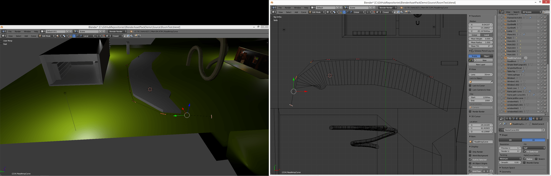
Well it seems you havn’t any idea how this curve deform modifier works aswell; but I did get slightly better results using one mesh, but the problem still persists with editing the curve when its inside the model thats using it, despite the fact that its data shouln’t be impacted by it…

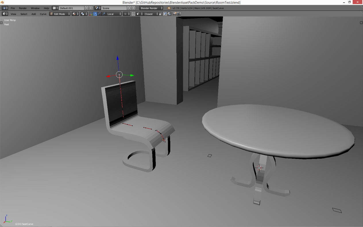
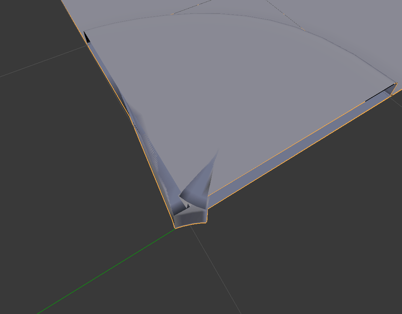
The deformation data isn’t totally accurate but provides rough control. Moving it to the center of the mesh causes the problem I mentioned though

One of the wierdest parts is that the rotation of the curves dont impact the mesh unless it is the first and last verticie of the spline.


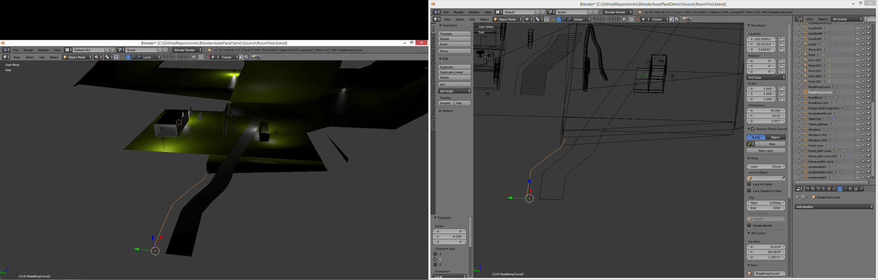
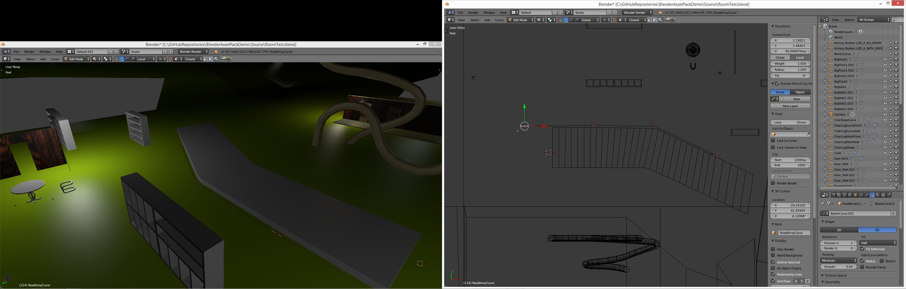
Hmm i think the workaround is to edit the curve when its not inside the mesh, then move it inside the mesh later for better accuracy. The problem with doing this is you can’t see the end results while working on the curve

The other problem is that rotating the curve verticies/handles doesnt impact the model unless its on the end… although, this doesn’t reflect what Mike showed in the video, so not sure whats causing this.


Edit: Ah! Its cuz i had snapping turned on :scream::astonished::astonished:

Very finicky method, and it still doesn’t explain the problem with the rotation of the handles, nor defines exactly why the position of the curve should be an issue


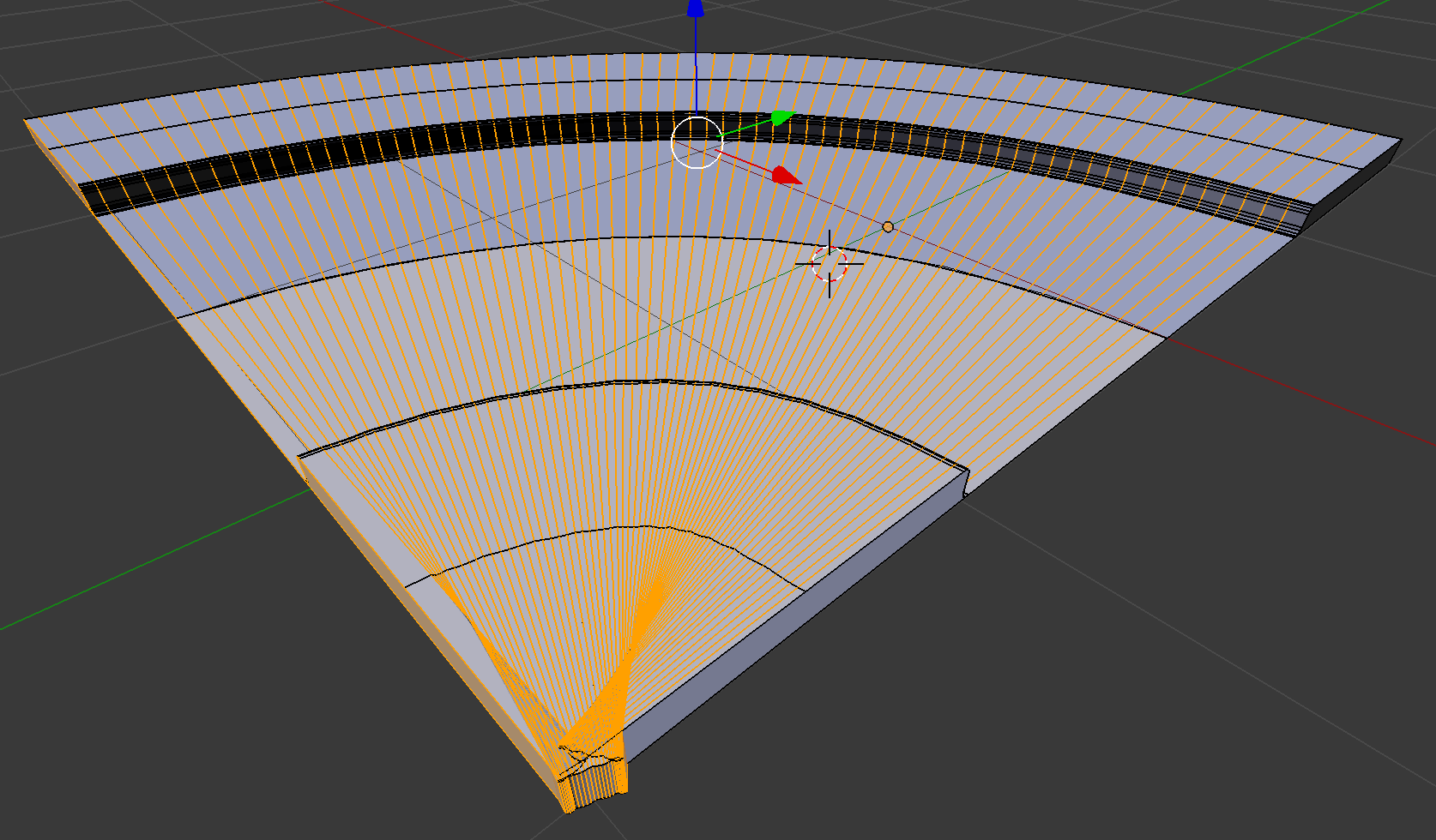
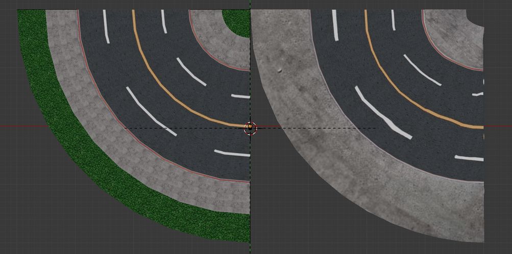
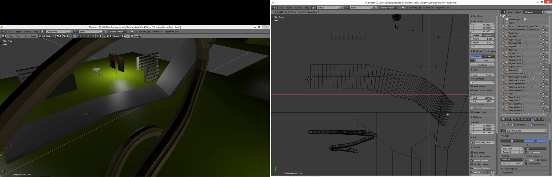
Edit: The reason the curves in the middle had no impact is because the curve resolution was still set to 1! But for deforming a mesh that isnt mirrored you want to have this control!


I would have solved this much quicker if Mike told us about the snap onto itself toggling for the snapping tool earlier! Even without that i still get some wierd results but at least the snapping tool is usable now, despite being midway through the course -_-


What terribly explained sets of lectures! Mike still hasn’t even explained to us the differnt types of curves or the fact that you can change their type or the fact that you can change how each verticie is edited!! Which causes alot of problems for anything that doesnt involve mimmicing the lectures EXACTLY how he does them including skipping the challenges!

wow this was very difficult. I don’t think this is the most conventional way to set up your architecture.
This isn’t the final version of my chair but its what it looks like by deforming a cube

Privacy & Terms