Addressing the top-of-pyramid 1m versus 2m discrepancy

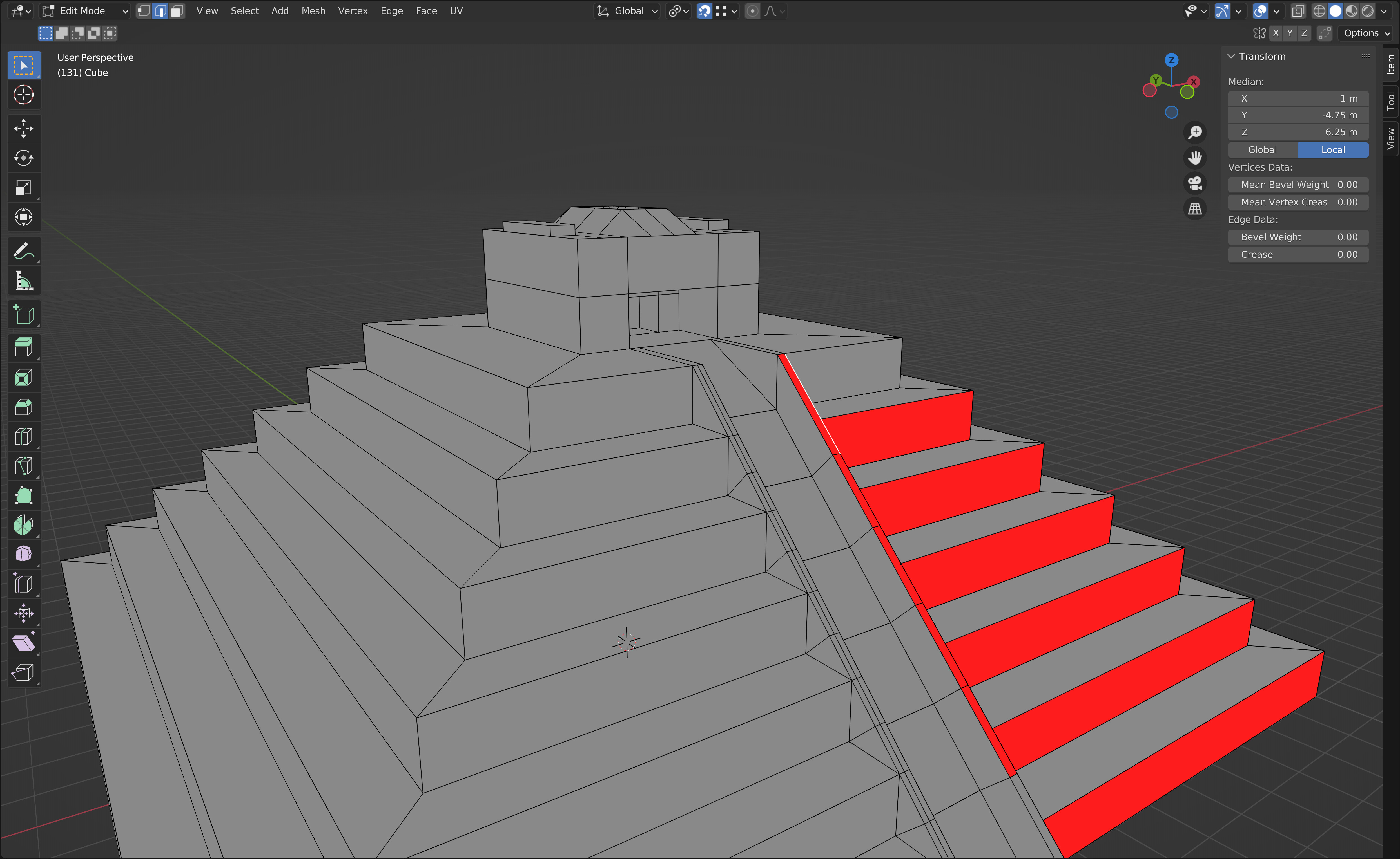
So I noticed that throughout the videos, the top-most step seemed to change relative size, from 2m to 1m.

This made following the suggested instructions difficult, so I wanted to share how I tackled it.

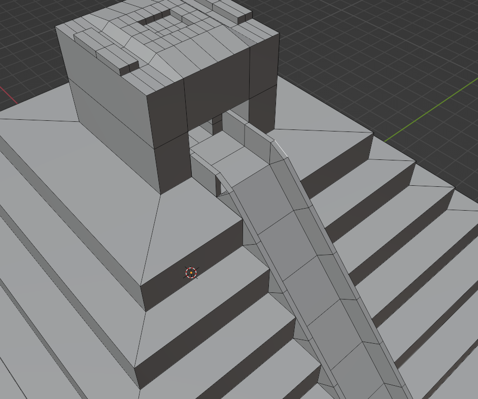
I deselected the flat segments of railing at the top and snap-extruded the angled segments as per the video. Afterwards, I extruded the flat segments by 0.75m, which is a number I figured out through a bit of trial and error. Afterwards, snap-extruding towards the inner doorway was fairly simple since it went along the same axis.

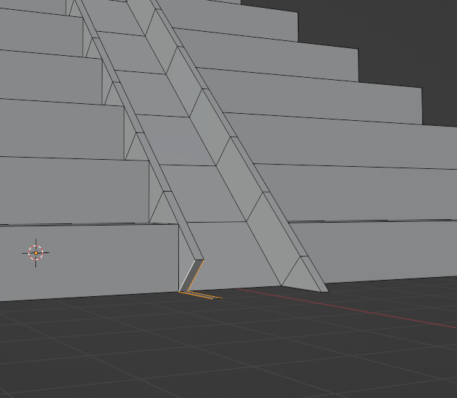
I did a similar thing at the bottom, realizing that thanks to the dimension specifications of this particular project, I could extrude the loop-cut edges at the bottom by 1m, and then fill in the face-gaps like I did with the top railing.

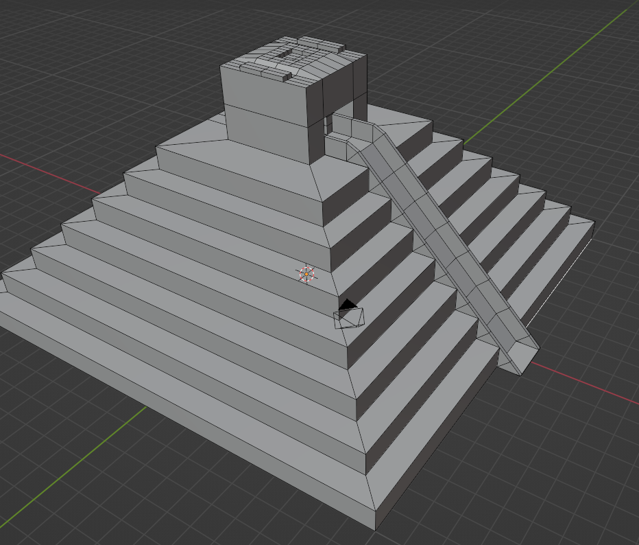
Rather than pictures of the completed result, I wanted to share what it looked like partway through my method, so that it’s easier to see what I mean.


1 Like

This is what it looked like when I finished. I decided to fill in the gap at the bottom for the sake of model consistency.

2 Likes

Well done seems you sorted out the problems you had very well.

I had same issues, which I sorted out a bit differently, as you can see. But the result is not passing the Blender’s Mesh Analysis (Show Overlays) for Intersects. I believe the problem is that the edges of the steps are not connected to the rail. See the right rail of my solution. I had to subdivide and align the new edges on the rail in order to fix that, as seen on my left rail. Not sure if this is the right way, but after my previous HARD learned lesson with the topology mismash I am very careful about that. I suppose that everyone who will switch the analysis on will have this problem. Or did I screwed something up?

1 Like

As far as I’m aware there’s no “wrong” way to do any of these lessons as long as you’re learning something.

2 Likes

Sure, learning a lot :). I also learned a few lessons back to care about these sort of things as I want to use my models in a game engine someday. When the Overlays were introduced and I checked my previous models, they all turned red pretty much completely. Learned a lot especially when I tried to fix them - not an easy task.

I assume, that Blender/3d soft does not like when a vertices “touches” edge or face to which it is not connected. On some models it is pretty hard to identify the problem because it looks fine all around.

It is easy. Edit Mode, A Select all, Shift N, Recalculate outside.
Only unusual shapes where outside is not obvious might you need to select the red faces and choose ‘flip’ instead.

Privacy & Terms